TM 9-2320-280-20-3
D-96
Change 1
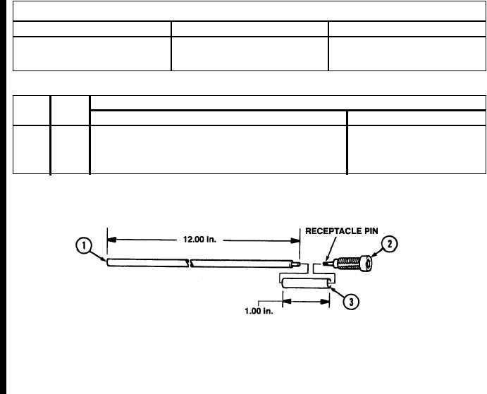
Figure D-109. Tip Jack Lead Assembly.
MATERIAL BLOCK
STOCK SIZE
DESCRIPTION
SPECIFICATION
14 AWG
WIRE, ELECTRICAL
MIL-C-13486/1
N/A
INSULATION SLEEVING
MIL-I-23053/5
Section II. ILLUSTRATED MANUFACTURING INSTRUCTIONS (Cont'd)
INSTRUCTIONS:
NOTE
When connecting electrical wire to receptacle pins on tip
jacks, use NSN 3493-00-133-1108 solder. (Refer to TB SIG-222
for soldering.)
1. Cut wire (1) into five 12-in. sections as shown.
2. Cut insulation sleeving (3) into five 1-in. sections as shown.
3. Connect five wires (1) to receptacle pins on tip jacks (2).
4. Place insulation sleeving (3) over wires (1) and receptacle pins and heat-shrink insulation sleeving (3)
into position.
ITEM
MATERIALS
NO.
REQ’D
DESCRIPTION
NSN
1
5
Electrical Wire: 12 in.
6145-00-152-6499
2
5
Tip Jack
5935-00-683-7651
3
5
Insulation Sleeving: 1 in.
5970-00-815-1295