TM 9-2320-387-24-l
4-6 1. DIRECTIONAL SIGNAL FLASHER REPLACEMENT
This task covers:
a. Removal
b. Installation
1
INITIAL SETUP:
Tools
General mechanic’s tool kit:
automotive (Appendix B, Item 1)
Materials/Parts
Sealing compound (Appendix C, Item 64)
Manual References
TM 9-2320-387-10
TM 9-2320-387-24P
Equipment Condition
Battery ground cables disconnected (para. 4-68).
Maintenance Level
Unit
NOTE
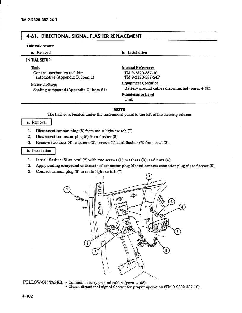
The flasher is located under the instrument panel to the left of the steering column.
vj
1.
Disconnect cannon plug (8) from main light switch (71.
2.
Disconnect connector plug (6) from flasher (5).
3.
Remove two nuts (41, washers (31, screws (11, and flasher (5) from cowl (2).
-1
Install flasher (5) on cowl (2) with two screws (11, washers (31, and nuts (4).
Apply sealing compound to threads of connector plug (6) and connect connector plug (6) to flasher
FOLLOW-ON TASKS: l Connect battery ground cables (para. 4-68).
l Check directional signal flasher for proper operation (TM 9-2320-387-10).
4-102