TM 9-2320-280-20-3
10-66. BODY REPAIR (Cont’d)
6. Blind Rivet Driving Practices and Precautions.
(a) Rivets should be inspected for proper installation. The grip length of each rivet is marked on top
of its head to provide positive identification. Use of proper grip length will produce a rivet
installation where locking collar is flush with top surface of rivet head. Tolerance limit on
flushness is 0.020 in. (0.5 mm).
(b) For proper rivet installation, it is imperative that holes be properly prepared, tools be in good
working order, and rivets properly applied. When problems occur, the source of trouble could be
in any of these areas.
7. Blind Rivet Installation.
NOTE
l Prior to installing blind rivets, the hole must be prepared, the
parts aligned and clamped firmly in place. These steps are the
same as for solid riveting operations. Proper drill sizes for
standard and oversized blind rivets are given in table 10-2.
Countersinking dimensions and minimum sheet gage for
countersunk blind rivets are shown in tables 10-3 and 10-4.
. It is very important that the proper length rivet is selected for
each application. Rivet lengths are sized by the range of material
thickness that the rivet will grip. Selecting the proper rivet
length is critical because rivets can tolerate only 1/16 inch
variation in material thickness for each particular rivet length.
Rivet grip lengths are called out as a “dash number” at the end
of the manufacturer’s part number. Grip lengths are determined
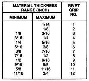
as shown in table 10-5.
l For double dimpled sheets, add countersunk head height to
materials thickness.
l Use rivet installation tool kit for all blind rivets.
Table 10-5. Rivet Grip Length Determination
10-109


