34-3. SUSPENSION ALIGNMENT INSTRUCTIONS (Cont'd)
NOTE
Caster and camber adjustments are basically the same for all
four wheels. This procedure covers the right front wheel.
1.
Remove wheel (para. 8-3).
2.
Remove two locknuts (7), washers (2), capscrews (1), and washers (2) from upper control arm (8)
and mounting brackets (3). Discard locknuts (7).
3.
Loosen two capscrews (6) and four nuts (5) on two mounting brackets (3) and airlift brackets (4).
NOTE
• When adjusting front and rear suspension camber, add or
subtract shims as matched sets under both upper control arm
mounting brackets.
• Shims are available in 0.060-in. (1.52-mm) and 0.120-in.
(3.05-mm) thicknesses.
4.
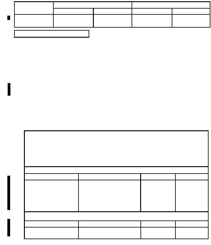
Add or subtract shim(s) (9) as required to bring caster and/or camber within specifications
(table 34-1). Suspension alignment change in relation to shim selection is shown in table 34-2.
b. Caster and Camber Adjustment
NOTE
• Subtracting shims will affect caster/camber in the opposite
direction as compared to adding shims.
• For 0.06 in. (1.52 mm) shims, reduce the values in the table by
half.
• For larger changes, combinations of additions or subtractions will
provide desired results.
FRONT SUSPENSION
LOCATION
SHIM (one each)
CASTER
CAMBER
Front and rear shims
+0.12 in. (3.05 mm)
0.0°
+0.5°
+0.06 in. (1.52 mm)
N/A
+0.5°
Front shim only
0.12 in. (3.05 mm)
+0.6°
+0.5°
0.06 in. (1.52 mm)
+0.3°
+0.3°
Rear shim only
0.12 in. (3.05 mm)
-0.6°
0.0°
0.06 in. (1.52 mm)
-0.3°
0.0°
Front and rear
0.12 in. (3.05 mm)
0.0°
+0.5°
0.06 in. (1.52 mm)
0.0°
+0.3°
Table 34-2. Suspension Alignment Change.
TM 9-2320-387-24-2
34-2
Change 1
REAR SUSPENSION
LOCATION
SHIM (one each)
CASTER
CAMBER
Table 34-1. Alignment Specifications.
CAMBER
CASTER
MODEL
FRONT
REAR
FRONT
REAR
M1113 (GVW)
0° (-2° to +2°)
.5° (-1° to +2°)
3° (0° to +4°)
N/A
M1114
0.5° (-2° to +2°)
1.3° (-1° to +2°)
2.3° (0° to +4°)
N/A