6-12. GEARED HUB SPINDLE BEARING ADJUSTMENT (Cont'd)
TM 9-2320-387-24-1
6-36
Change 1
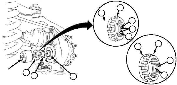
NOTE
For new configuration, two locktabs on lockwasher must be bent
away from retaining nut for removal.
3.
Bend locktab(s) (5) on lockwasher (2) away from retaining nut (3).
4.
Using retaining nut wrench, remove retaining nut (3) and lockwasher (2) from spindle (1). Discard
lockwasher (2).
NOTE
If four-slotted retaining nut TN-07 is present, it is recommended
to replace it with eight-slotted retaining nut 12342680.
5.
Apply grease to face of retaining nut (3) and install lockwasher (2) and retaining nut (3) on
spindle (1).
6.
Using retaining nut wrench, tighten retaining nut (3) to 35-45 lb-ft (47-61 N•m).
7.
Rotate spindle (1) five full rotations clockwise and five full rotations counterclockwise to properly
seat bearings.
8.
Loosen retaining nut (3) until it is finger-tight, then retighten nut to 23-27 lb-ft (31-37 N•m).
WARNING
Ensure locktab on lockwasher is bent completely into slot on
retaining nut. Eight-slotted retaining nut provides additional
security by enabling two locktabs on lockwasher to be bent into
slots on retaining nut. Failure to do this may cause injury to
personnel or damage to equipment.
NOTE
• For new configuration, two locktabs on lockwasher must be
bent into slots on retaining nut.
• It may be necessary to slightly loosen or tighten retaining nut
to gain proper alignment with locktabs.
9.
Determine which locktab(s) (5) on lockwasher (2) aligns with slot(s) (4) in retaining nut (3). Bend
locktab(s) (5) into slot(s) (4) on retaining nut (3).
1
3
2
2
3
4
5
4
2
3
4
5
RETAINING NUT
WRENCH
NEW
CONFIGURATION