TM 9-2320-387-24-l
l-23. BATTERY SYSTEM OPERATION
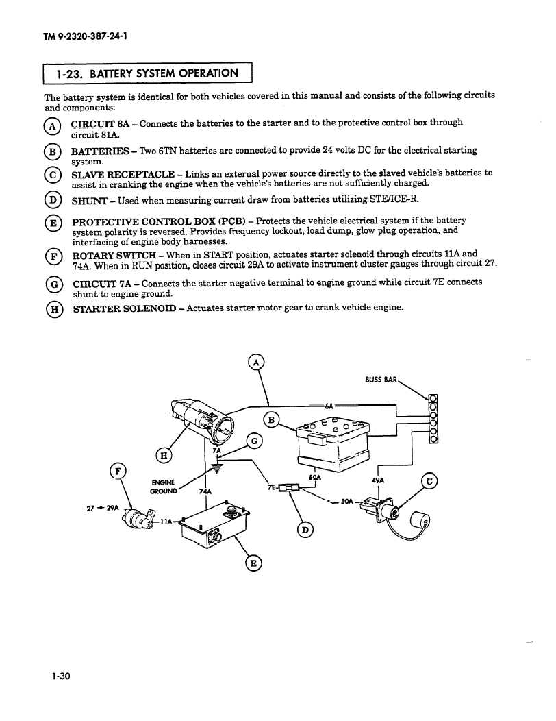
The battery system is identical for both vehicles covered in this manual and consists of the following circuits
and components:
0 A
0 B
0 C
0 D
0 E
0 F
0 G
0 H
CIRCUIT 6A - Connects the batteries to the starter and to the protective control box through
circuit 8%
BATTERIES - Two 6TN batteries are connected to provide 24 volts DC for the electrical starting
system.
SLAVE RECEPTACLE - Links an external power source directly to the slaved vehicle’s batteries to
assist in cranking the engine when the vehicle’s batteries are not suffkiently charged.
SHUNT - Used when measuring current draw from batteries utilizing STEACE-R.
PROTECTIVE CONTROL BOX (PCB) - Protects the vehicle electrical system if the battery
system polarity is reversed. Provides frequency lockout, load dump, glow plug operation, and
interfacing of engine body harnesses.
ROTARY SWITCH - When in START position, actuates starter solenoid through circuits 1lA and
744. When in RUN position, closes circuit 29A to activate instrument cluster gauges through circuit 27.
CIRCUIT 7A - Connects the starter negative terminal to engine ground while circuit 7E connects
shunt to engine ground.
STARTER SOLENOID - Actuates starter motor gear to crank vehicle engine.
27 *
l-30