TM 9-2320-387-24-l
f-
1
.-
1 l-22.
GENERATING SYSTEM OPERATION
1
I
I
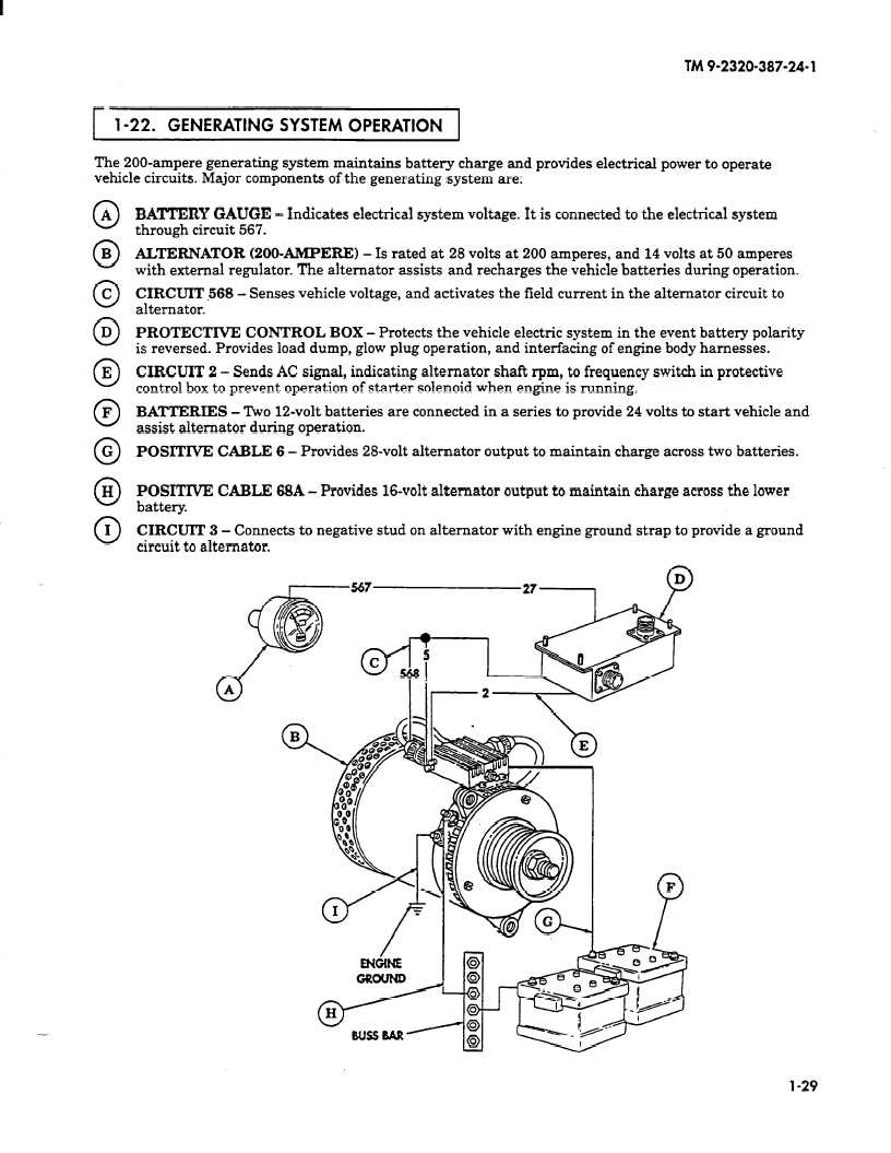
The 200-ampere generating system maintains battery charge and provides electrical power to operate
vehicle circuits. Major components of the generating system are:
0 A
0
B
0
C
0
D
0
E
0
F
0
G
0
H
0
I
BATTERY GAUGE - Indicates electrical system voltage. It is connected to the electrical system
through circuit 567.
ALTERNATOR (ZOO-AMPERE1 - Is rated at 28 volts at 200 amperes, and 14 volts at 50 amperes
with external regulator. The alternator assists and recharges the vehicle batteries during operation.
CIRCUIT 568 - Senses vehicle voltage, and activates the field current in the alternator circuit to
alternator.
PROTECTIVE CONTROL BOX - Protects the vehicle electric system in the event battery polarity
is reversed. Provides load dump, glow plug operation, and interfacing of engine body harnesses.
CIRCUIT 2 - Sends AC signal, indicating alternator shaft rpm, to frequency switch in protective
control box to prevent operation of starter solenoid when engine is running.
BATTERIES - Two 12-volt batteries are connected in a series to provide 24 volts to start vehicle and
assist alternator during operation.
POSITIVE CABLE 6 - Provides 28-volt alternator output to maintain charge across two batteries.
POSITIVE CABLE 68A - Provides 16-volt alternator output to maintain charge across the lower
battery.
CIRCUIT 3 - Connects to negative stud on alternator with engine ground strap to provide a ground
circuit to alternator.
l-29

