REFERENCE INFORMATION
-I
I
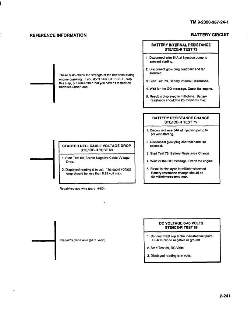
These tests check the strength of the batteries during
engine cranking.
If you don’t have STUICE-R,
skip
this step, but remember that you haven’t tested the
batteries under load.
STARTER NEG. CABLE VOLTAGE DROP
STE/lCE-R TEST 69
1. Start Test 69, Starter Negative Cable Voltage
Drop.
2. Displayed reading is in volt. The cable voltage
drop should be less than 0.25 volt max.
Repair/replace
wire (para. 4-80).
-I Repair/replace
wire (para. 4-60).
TM 9-2320-387-24-1
BAITERY CIRCUIT
BAlTERY INTERNAL RESISTANCE
STOICE-R TEST 73
1. Diinnect
wire 54A at injection pump to
prevent starting.
2. Disconnect glow plug controller and fan
solenoid.
3. Start Test 73, Battery Internal Resistance.
4. Wait for the GO message. Crank the engine.
5. Result is displayed in milliihms.
Battery
resistance should be 25 milliohms max.
BATTERY RESISTANCE CHANGE
STUICE-R TEST 75
1. Disconnect wire 54A at injection pump to
prevent starting.
2. Disconnect glow plug controller and fan
solenoid.
3. Start Test 75, Battery Resistance Change.
4. Wait for the GO message. Crank the engine.
5. Result is displayed in milliohms&cond.
Battery resistance change should be
50 milliohms/second
max.
DC VOLTAGE O-45 VOLTS
STEIICE-R TEST 69
1. Connect RED clip to the indicated test point,
BLACK clip to negative or ground.
2. Start Test 69, DC Volts.
3. Displayed reading is in volts.
2-241