1
2
3
4
5
TM 9-2320-387-24-1
7-36
Change 1
7-12. SERVICE BRAKE ROTOR REPLACEMENT
This task covers:
a. Removal
b. Installation
Manual References
TM 9-2320-387-24P
Equipment Condition
Service brake caliper removed (para. 7-4).
Maintenance Level
Unit
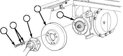
a. Removal
1.
Remove six capscrews (1) and two-piece lockwashers (2) from halfshaft (3), rotor (4), and output
flange (5).
NOTE
Clean excess sealant from output flange threaded holes with
a 10 mm tap.
2.
Disconnect halfshaft (3) and remove rotor (4) from output flange (5).
b. Installation
NOTE
• New capscrews come with preapplied thread-locking compound,
however, still apply sealing compound to threads of new
capscrews. If old capscrews are to be used, mating threads must
be cleaned and sealing compound applied to threads of
capscrews.
• Two-piece lockwashers must be installed in sets of two with
serrated sawtooth threads facing each other.
1.
Apply sealing compound to threads of six capscrews (1).
2.
Install rotor (4) on output flange (5).
3.
Install halfshaft (3) on rotor (4) with six two-piece lockwashers (2) and capscrews (1). Tighten
capscrews (1) to 58 lb-ft (79 N•m).
FOLLOW-ON TASK: Install service brake caliper (para. 7-4).
INITIAL SETUP:
Tools
General mechanic’s tool kit:
automotive (Appendix B, Item 1)
Maintenance and repair shop equipment:
automotive (Appendix B, Item 2)
Materials/Parts
Sealing compound (Appendix C, Item 63)
Six two-piece lockwashers
(Appendix G, Item 240.1)