TM 9-2320-280-20-3
11-212. BLOWER ASSEMBLY REPLACEMENT (Cont’d)
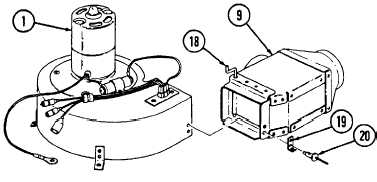
Remove four rivets (20), diverter box (9), and foot (19) from blower assembly (1).
1.
2.
3.
4.
5.
6.
Install diverter box (9) and foot (19) on blower assembly (1) with four rivets (20).
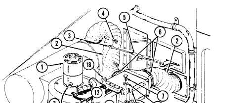
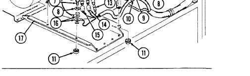
Install blower assembly (1), harness clamp (10), and two ground terminals (16) on bracket (17) with
four washers (8), capscrews (7), and nut and lockwasher assemblies (11).
Connect leads 770 (13), 771 (14), and 772 (15) to blower motor leads (12).
Place lever on heat/vent control panel in UNIT OFF position (TM 9-2320-280-10). Turn adjustable
end (3) of control linkage (5) so that diverter box arm (18) is installed all the way forward
(toward blower motor) when adjustable end (3) iS installed on diverter box arm (18).
Install control linkage (5) on diverter box arm (18) with pushnut (4).
Install two hose ducts (2) on diverter box (9) and tighten clamps (6).
FOLLOW-ON TASKS: . Install heater compartment panel (para. 11-204).
l Connect battery ground cable (para. 4-73).
l Check blower for proper operation (TM 9-2320-280-10).
11-322