WARNING
TM 9-2320-280-20-1
REFERENCE INFORMATION
Change 1 2-263
STARTER CIRCUIT
BAD CONNECTIONS ARE THE MOST COMMON
PROBLEM !
Sometimes, just disconnecting, cleaning and
reconnecting will solve a problem. BE THOROUGH!
The time you save may be your own.
Refer to the functional flow schematic and check the
following:
1. BATTERY - make sure all connections are clean
and tight, including the shunt and power stud.
2. STARTER - check the high current (heavy gauge
wire 6A) wire at the starter. Don't just check for
voltage; a loose connection will have voltage but
can't carry much current.
A cold engine should crank at least 100 RPM.
A warm engine should crank at least 180 RPM.
BATTERY VOLTAGE
1. Start Test 67, battery voltage.
2. Displayed reading is in volts. Batteries should
be 23-25.5 volts. Batteries voltage will drop when
glowplugs turn on.
BATTERY VOLTAGE
MULTIMETER
1. Set the voltmeter to a DC volts scale of at least
40 volts.
2. Connect the RED lead to positive and the
BLACK lead to negative.
3. Be sure to read the correct scale.
STE/ICE-R TEST 67
RED
YELLOW
GREEN
RED
VOLTS
+
-
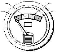
VOLTS
GAUGE
Disconnect negative battery cable before dis-
connecting and reconnecting protective control
box/distribution box harness.
There is battery voltage at the PCB/distribution box
at all times. Failure to disconnect battery cable will
result in damage to equipment or injury to
personnel.
3. PROTECTIVE CONTROL BOX/
DISTRIBUTION BOX - Unscrew BOTH connectors
and look for bent or broken pins, pins pushed out of
their socket, or dirt and corrosion in the connections.
4. ROTARY SWITCH - Check the wires at the switch.
Don't just look. Feel the connections to make sure
they're snug. Many problems can be solved by
seeing with your fingers, not just your eyes.
2