REFERENCE INFORMATION
TM 9-2320-280-20-1
BATTERY CIRCUIT
BATTERY INTERNAL RESISTANCE
STE/ICE-R TEST 73
Replace batteries, refer to (para 4-79).
NOTE
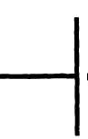
Check these cables
WIRE 68, correcting the batteries
together. Test point is the positive
terminal of one of the batteries.
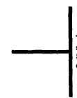
WIRE 49A, connecting the battery to
the power stud. Test point is the
power stud.
Wire connecting the battery to the
shunt. Test point is the negative
terminal of the battery.
Wire connecting shunt to ground stud.
Test point is the shunt.
Replace batteries, refer to (para 4-79).
NOTE
Tests 77 and 79 are TK tests that do the
same thing that DCA tests 73 and 75 do.
See TM 9-4910-571-12&P for instructions
on how to run these tests.
1. Disconnect wire 54A at injection pump to
prevent starting.
2. Disconnect glowplug controller and fan
solenoid (to keep waveform clean).
3. Start Test 73, battery internal resistance.
4. Wait for the GO message. Crank the
engine.
5. Result is displayed in milliohms. Battery
resistance should be 25 milliohms max.
BATTERY RESISTANCE CHANGE
STE/ICE-R TEST 75
1. Disconnect wire 54A at injection pump to
prevent starting.
2. Disconnect glowplug controller and fan
solenoid (to keep waveform dean).
3. Start Test 75, battery resistance change.
4. Wait for the GO message. Crank the engine.
5. Result is displayed in milliohms/second.
Battery resistance change should be
50 milliohms/second max.
0-45 DC VOLTS
STE/lCE-R TEST 89
1. Connect RED clip to the indicated test point,
BLACK dip to negative or ground.
2. Start Test 89, DC volts.
3. Displayed reading is in volts.
2-259/(2-260 Blank)