REFERENCE
TM 9-2320-387-24-I
INFORMATION
STARTER ClRCUlT
0 II
. l
I
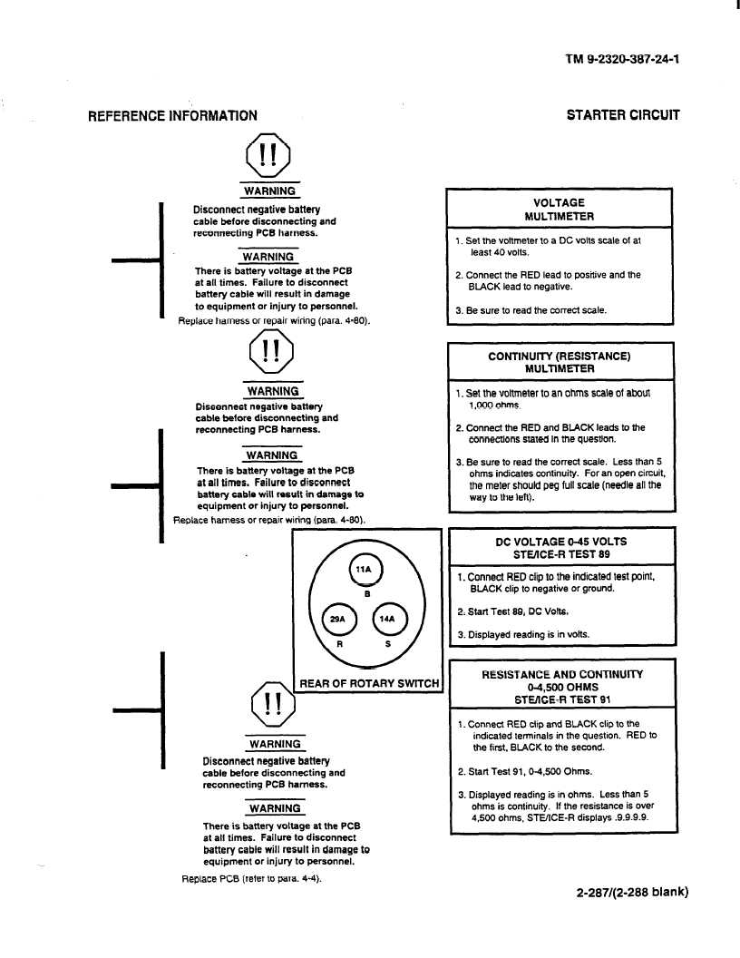
WARNING
Disconnect negative battery
cable before disconnecting
and
reconnecting PCB harness.
WARNING
There is battery voltage at the PC6
at all times. Failure to disconnect
battery cable will result in damage
to equipment or injury to personnel.
Replace harness or repair wiring (para. 4-80).
n
0 II
. .
WARNING
Disconnect negative battery
cable before disconnecting
and
reconnecting
PCB harness.
WARNING
There is battery voltage at the PCB
at all times. Failure to disconnect
battery cable will result in damage to
equipment or injury to personnel.
Replace harness or repair wiring (Pam. 4-80).
b
REAR OF ROTARY SWlTCl-
WARNING
Disconnect negative battery
cable before disconnecting
and
reconnecting
PC6 harness.
WARNING
There is battery voltage at the PCB
at all times. Failure to disconnect
battery cable will result in damage to
equipment or injury to personnel.
Replace PCB (refer to para. 4-4).
VOLTAGE
MULTlMETER
1. Set the voltmeter to a DC volts scale of at
least 40 volts.
2. Connect the RED lead to positive and the
BLACK lead to negative.
3. Be sure to read the correct scale.
CONTINUITY (RESISTANCE)
MULTIMETER
1. Set the voltmeter to an ohms scale of about
1,000 ohms.
2. Connect the RED and BLACK leads to the
connections stated in the question.
3. Be sure to read the correct scale. Less than 5
ohms indicates continuity. For an open circuit.
the meter should peg full scale (needle all the
way to the left).
DC VOLTAGE O-45 VOLTS
STEIICE-R TEST 89
I
1. Connect RED clip to the indicated test point,
BUCK
clip to negative or ground.
2. Start Test 89, DC Volts.
3. Displayed reading is in volts.
RESISTANCE AND CONTINUITY
04,500 OHMS
STE/lCE-R TEST 91
I
1. Connect RED ctip and BLACK clip to the
indicated terminals in the question. RED to
the first, BlACK to the second.
2. Start Test 91,0-4,500
Ohms.
3. Displayed reading is in ohms. Less than 5
ohms is continuity. If the resistance is over
4,500 ohms, STE/ICE-R displays .9.9.9.9.
2-287/(2-288 blank)