REFERENCE INFORMATION
STARTER CIRCUIT
0 II
. .
I
WARNING
I
Disconnect negative battery
cable before disconnecting and
reconnecting PC0 harness.
1
WARNING
There is battery voltage
at the PCB
at all times. Failure to disconnect
battery cable will result in damage to
equipment or injury to personnel.
Check the wires and connections at both ends for
broken wires or any kind of bad connection.
Repair whatever you can. If the wires and
connections seem ok, you have to replace the
harness.
Repair wiring or replace harness (para. 4-80).
-I
Replace rotary switch (para. 4-10).
I
1
I
DC VOLTAGE O-45 VOLTS
STUICE-R TEST 89
I
1. Connect RED clip to the indicated test point,
BLACK clip to negative or ground.
2. Start Test 89. DC Volts.
3. Displayed reading is in volts.
VOLTAGE
MULTIMETER
1. Set the voltmeter to a DC volts scale of at least
40 volts.
2. Connect the RED lead to positive and the
BLACK lead to negative.
3. Be sure to read the correct scale.
TM 9-2320-387-24-l
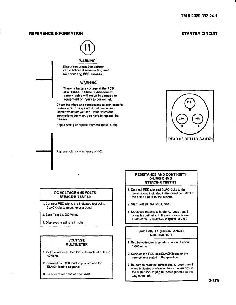
REAR OF ROTARY SWlTCH
RESISTANCE AND CONTINUITY
04,500 OHMS
STEXE-R
TEST 91
1. Connect RED clip and BLACK clip to the
terminations indicated in the question.
RED to
the first, BLACK to the second.
/ 2.StartTest91,0-4,8000hms.,
.
1
3. Displayed reading is in ohms. Less than 5
ohms is continuity.
If the resrstance IS over
4.500 ohms, STUICE-R
displays .9.9.9.9.
CONTINUITY (RESISTANCE)
MULTIMETER
1. Set the voltmeter to an ohms scale of about
1,000 ohms.
2. Connect the RED and BLACK leads to the
connections stated in the question.
3. Be sure to read the correct scale. Less than 5
ohms indicates continuity.
for an open circuit,
the meter should peg full scale (needle all the
way to the left).
2-279