TM 9-2320-387-24-l
REFERENCE INFORMATION
STARTER CIRCUIT
The connections for the neutral safety
switch can be reached by removing the
-engine cover. The connections are near
I
the gear shift lever.
Replace neutral safety switch (refer to para. 5-6).
0 II . .
WARNING
Disconnect negative battery cable
before disconnecting and reconnecting
PCB harness.
WARNING
There is battery voltage at the PCB at all
times. Failure to disconnect battery cable
will result in damage to equipment or injury
to personnel.
Repair wiring (para. 4-60) or replace switch (para. 5-6).
DC VOLTAGE
O-45 VOLTS
STVICE-R
TEST 88
1. Connect RED clip to the indicated test
point, BLACK clip to negative or ground.
2. Start Test 69, DC volts.
3. Displayed reading is in volts.
VOLTAGE
MULTIMETER
1. Set the voltmeter to a DC volts scale of at least
40 volts.
2. Connect the RED lead to positive and the
BLACK lead to negative.
I
3. Be sure to read the correct scale.
CONTINUITY
(RESISTANCE)
MULTlMETER
1. Set the vottmeter to an ohms scale of about
1.000 ohms.
2. Connect the RED and BLACK leads to the
connections stated in the question.
3. Be sure to read the correct scale. Less than 5
ohms indicates continuity.
For an open circuit,
the meter should peg full scale (needle all the
way to the left).
I RESISTANCE
AND CONTINUITY
I
04.5DO OHMS
STE/lkE-R
TEST 81
1. Connect RED clip and BLACK clip to the
terminations indicated in the question.
RED
to the first, BLACK to the second.
I
2. Start Test 91,0-4.500
Ohms.
3. Displayed reading is in ohms. Less than 5
ohms is continutty.
If the resistance is over
4.500 ohms, STEACE-R displays .9.9.9.9.
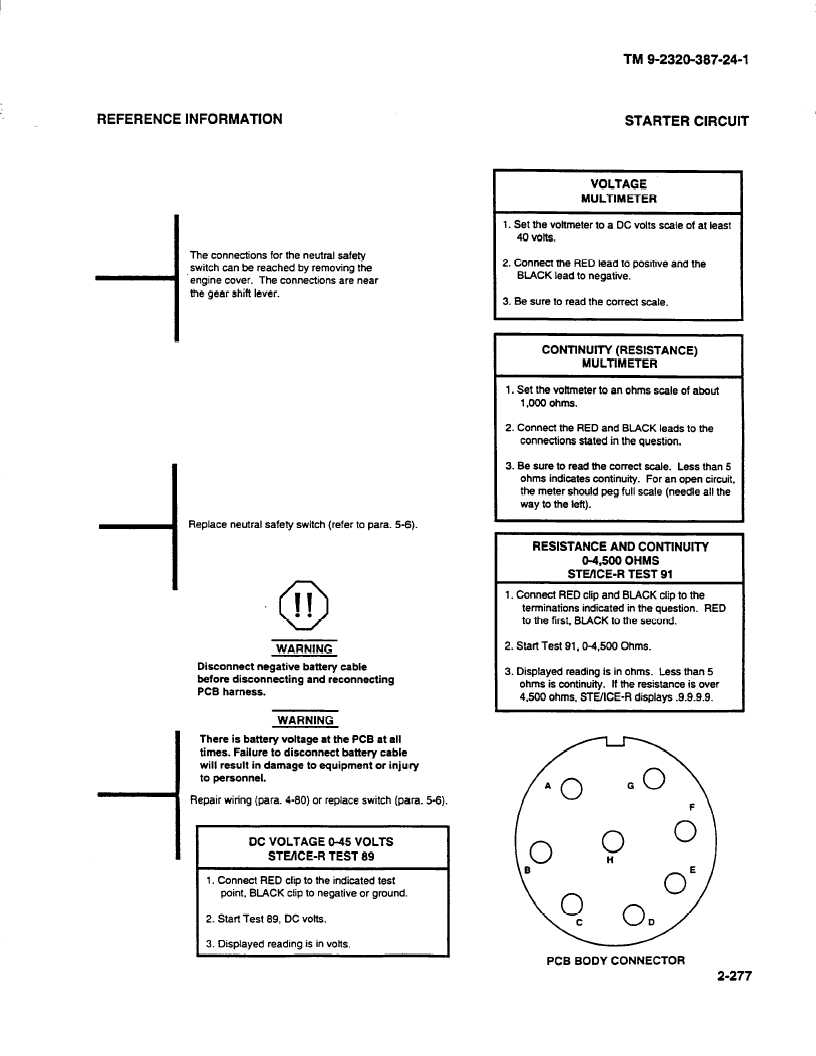
PCB BODY CONNECTOR
2-277