TM 9-2320-387-24-l
REFERENCE INFORMATION
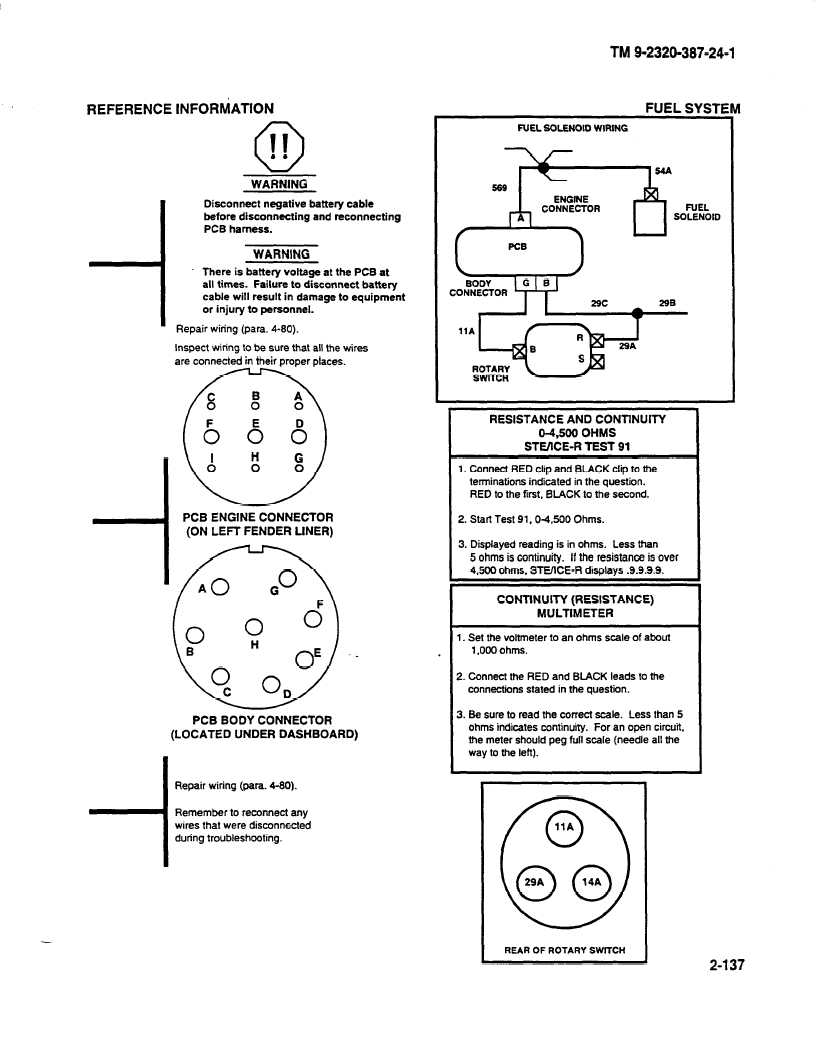
0 II . .
WARNING
Disconnect negative battery cable
before disconnecting and reconnecting
PCB harness.
WARNING
There is battery voltage at the PCB at
all times. Failure to disconnect battery
cable will result in damage to equipment
or injury to personnel.
Repair wiring (para. 4-80).
Inspect wiring to be sure that all the wires
are connected in their proper places.
PCB ENGINE CONNECTOR
(ON LEFT FENDER LINER)
PCB BODY CONNECTOR
(LOCATED UNDER DASHBOARD)
I
Repair wiring (para. 4-80).
Remember to reconnect any
wires that were disconnected
I
during troubleshooting.
-
FUEL SGLENOID WIRING
FUEL
SOLENOID
RESISTANCE AND CONTlNUlTY
04.500 OHMS
STUICE-R TEST 91
I
1. Connect RED clip and BLACK clip to the
terminations indicated in the question.
RED to the first, BLACK to the second.
CONTINUITY (RESISTANCE)
MULTIMETER
1. Set the voltmeter to an ohms scale of about
1,000 ohms.
2. Connect the RED and BLACK leads to the
connectiins
stated in the question.
3. Be sure to read the correct scale. Less than 5
ohms indicates continuity. For an open circuit,
the meter should peg full scale (needle all the
way to the left).
REAR OF ROTARY SWITCH
2-137