TM 9-2320-362-14&P
4-18. EES KIT INSTALLATION (Cont’d)
7.
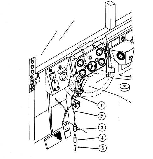
From engine side, route wire no.
28 (2) through cowl grommet (1)
behind 200 amp alternator.
8.
Slide rubber shell (3) and plastic sleeve (4) from connector onto
wire no. 28 (2).
9.
Strip insulation 1/4-inch (0.64 cm) from end of wire no. 28 (2).
10.
Install connector terminal (5) onto wire no. 28 (2) and crimp.
WARNING
To prevent eye injury, wear protective eye wear
while performing any soldering.
11.
Solder crimped joint between connector terminal (5) and wire
no. 28 (2).
12.
Slide plastic sleeve (4) and rubber shell (3) onto connector
terminal (5).
4-74

