TM 9-2320-280-20-2
4-106
Change 2
4-65. DIRECTIONAL SIGNAL CONTROL REPLACEMENT
a. Removal
1.
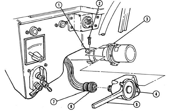
Loosen connector nut (6) and remove connector plug (7) from directional signal control (4).
2.
Remove four screws (2) and directional signal control (4) from bracket (1).
INITIAL SETUP:
Applicable Models
M997A2, M1025A2, M1035A2, M1043A2,
M1045A2, M1097A2, M1123
Tools
General mechanic’s tool kit:
automotive (Appendix B, Item 1)
Manual References
TM 9-2320-280-10
TM 9-2320-280-24P
Equipment Condition
Battery ground cables disconnected (para. 4-73).
1.
Place lever (5) in HAZARD position.
2.
Install directional signal control (4) on bracket (1) with four screws (2). Do not tighten screws (2).
3.
Rotate steering wheel ensuring pin (3) mates with directional signal control (4) and tighten screws (2)
to 22-26 lb-in. (2.5-2.9 N•m).
4.
Install connector plug (7) on directional signal control (4) and tighten connector nut (6).
b. Installation
This task covers:
a. Removal
b. Installation
FOLLOW-ON TASKS: • Connect battery ground cables (para. 4-73).
• Check directional signal control lamp for proper operation (TM 9-2320-280-10).