3-61. RADIATOR AND FAN SHROUD ASSEMBLY MAINTENANCE (Cont’d )
TM 9-2320-280-20-2
3-114
Change 2
NOTE
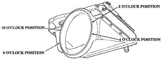
• Fan shroud should be aligned so the following dimensions are
maintained. Adjustments may be made by sliding the radiator/
shroud assembly. Distance “A” from the edge of shroud ring and rear
edge of fan must be 1-1/2 ± 1/8 in. (38.1 ± 3 mm). Measure distance
“A” at the 2, 4, 8, and 10 o'clock positions.
• Fan blade to fan shroud clearance, the distance between the top of the
fan blade and fan shroud, must not be less than 1/4 in. (6 mm) at any
position.
6.
Tighten locknuts (12) to 26 lb-ft (35 N•m). Tighten capscrew (9) to 30 lb-ft (41N•m).
NOTE
• To secure strap to shroud, use of rivet is optional.
• Perform steps 7.1 and 7.2 if retaining strap was not connected to
radiator shroud with rivet.
7.
Secure radiator (3) to shroud (13) with strap (5). Secure strap (5) to shroud (13) with rivet (4).
7.1.
Locate, mark, and drill 0.129-in. (3 mm) diameter hole (using #30 drill bit) in strap (5) and fan
shroud (13). Remove burrs and sharp edges.
7.2.
Secure radiator (3) to fan shroud (13) with rivet (4).
8.
Connect lower radiator front hose (11) to radiator (3) with clamp (10).
NOTE
• M1123 and “A2” vehicles have a quick-disconnect on fan drive hose.
• The fan drive hose may be modified to add the quick-disconnect.
Refer to appendix D, Fig. D-94 for installation.
9.
Connect fan drive hose (17) to fan drive (18).
10.
Connect control valve hose (14) to bulkhead adapter (16) with clamp (15).
NOTE
For vehicles equipped with a 200 amp alternator, it is recommended
that the inlet hose be installed with the hose twisted counterclockwise,
and upward until a kink in the hose starts to form.
11.
Connect radiator inlet hose (1) to radiator (3) with clamp (2).
12.
Connect surge tank-to-radiator vent hose (6) to adapter (8) with clamp (7).