TM 9-2320-280-20-1
REFERENCE INFORMATION
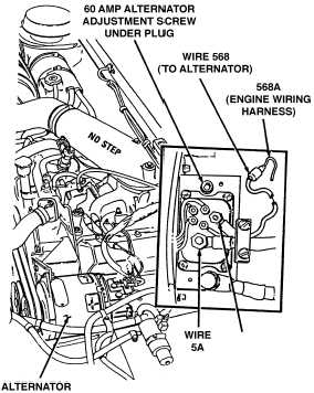
ALTERNATOR
Change 1 2-207
1. Turn engine off.
2. Remove protective cover from alternator wiring.
3. Remove the potting material.
4. Remove hex head plug to expose adjustment screw.
5. Start engine and lock throttle at 1200-1500 RPM by
using STE/ICE-R test 10.
6. Connect the Red test lead to wire 5A and the Black
lead to engine ground.
7. Monitor alternator output voltage with STE/ICE-R
test 89.
8. Use a cross tip screwdriver to adjust the alternator
output voltage 28.0 ± 0.5 Volts.
9. Unlock throttle, replace hex head plug, repot the area
with silicon caulk, and replace the protective cover.
ENGINE RPM
STE/ICE-R TEST 10
1. Start Test 10, Engine RPM.
2. Crank or start the engine. Displayed reading is
RPM. Cranking RPM should be approximately 100.
Idle RPM should be 625-675.
0-45 DC VOLTS
STE/ICE-R TEST 89
1. Connect RED clip to the indicated test point,
BLACK clip to negative or ground.
2. Start Test 89, DC volts.
3. Displayed reading is in volts.
NOTE
Regulator cannot be tested independently from
alternator on 60 amp alternator system.
WIRE
2A