TM 9-2320-387-24-2
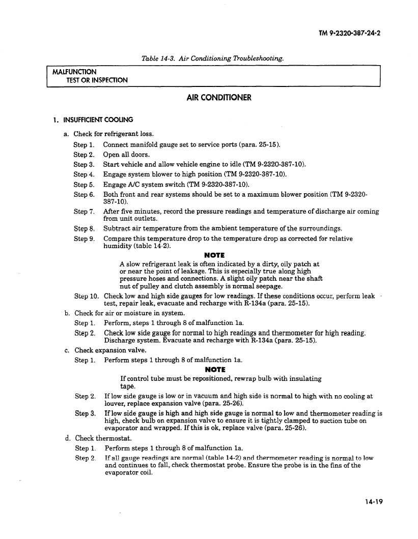
Table 14-3. Air Conditioning
lkoubleshooting.
TEST OR INSPECTION
AIR CONDITIONER
1. INSUFFICIENT COOUNG
a. Check for refrigerant loss.
Step 1.
Step 2.
step 3.
Step 4.
Step 5.
Step 6.
Step 7.
Step 8.
Step 9.
Connect manifold gauge set to service ports (para. 25-15).
Open all doors.
Start vehicle and allow vehicle engine to idle (TM 9-2320-387-10).
Engage system blower to high position (TM 9-2320-387-10).
Engage A/C system switch (TM 9-2320-387-10).
Both front and rear systems should be set to a maximum blower position (TM 9-2320-
387-10).
After five minutes, record the pressure readings and temperature of discharge air coming
from unit outlets.
Subtract air temperature from the ambient temperature of the surroundings.
Compare this temperature drop to the temperature drop as corrected for relative
humidity (table 14-2).
NOTE
A slow refrigerant leak is often indicated by a dirty, oily patch at
or near the point of leakage. This is especially true along high
pressure hoses and connections. A slight oily patch near the shaft
nut of pulley and clutch assembly is normal seepage.
Step 10. Check low and high side gauges for low readings. If these conditions occur, perform leak
test, repair leak, evacuate and recharge with R-134a tpara. 25-15).
b. Check for air or moisture in system.
Step 1.
Perform, steps 1 through 8 of malfunction la.
step 2.
Check low side gauge for normal to high readings and thermometer for high reading.
Discharge system. Evacuate and recharge with R-134a (para. 25-15).
c. Check expansion valve.
step 1.
Perform steps 1 through 8 of malfunction la.
NOTE
If control tube must be repositioned, rewrap bulb with insulating
tape.
Step 2.
If low side gauge is low or in vacuum and high side is normal to high with no cooling at
louver, replace expansion valve (para. 25-26).
step 3.
If low side gauge is high and high side gauge is normal to low and thermometer reading is
high, check bulb on expansion valve to ensure it is tightly clamped to suction tube on
evaporator and wrapped. If this is ok, replace valve (para. 25-26).
d. Check thermostat.
Step 1.
Perform steps 1 through 8 of malfunction la.
Step 2.
If all gauge readings are normal (table 14-2) and thermometer reading is normal to low
and continues to fall, check thermostat probe. Ensure the probe is in the fins of the
evaporator coil.
14-19