REFERENCE INFORMATION
INSTRUMENTS CIRCUIT
TM 9-2320-387-24-l
-I
-1
I
DC VOLTAGE O-45 VOLTS
STMCE-R TEST 89
1. Connect RED clip to the indicated test point,
BLACK clip to negative or ground.
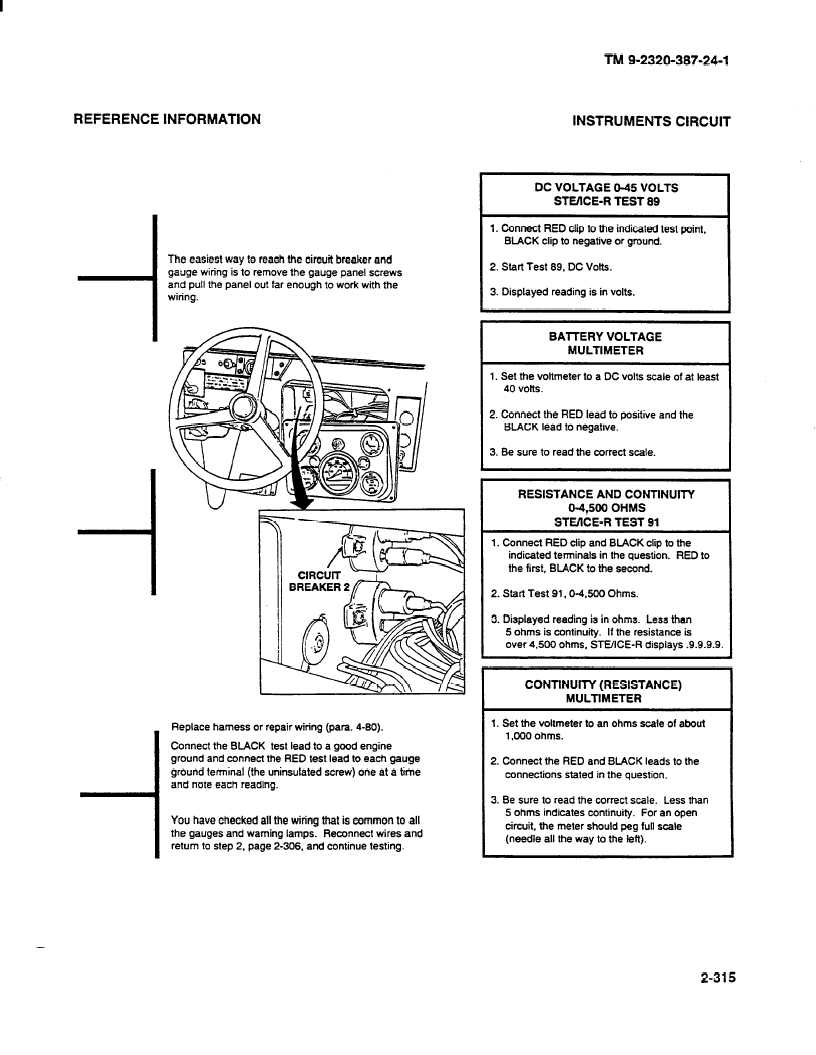
The easiest way to reach the circuit breaker and
gauge wiring is to remove the gauge panel screws
and pull the panel out far enough to work with the
wiring.
2. Start lest 89, DC Volts.
3. Displayed reading is in volts.
Replace harness or repair wiring (para. 4-90).
Connect the BLACK test lead to a good engine
ground and connect the RED test lead to each gauge
ground terminal (the uninsulated screw) one at a time
and note each reading.
You have checked all the wiring that is common to all
the gauges and warning lamps. Reconnect wires and
return to step 2. page 2-306. and continue testing.
BAITERY VOLTAGE
MULTIMETER
1. Set the voltmeter to a DC volts scale of at least
40 volts.
2. Connect the RED lead to positive and the
BLACK lead to negative.
3. Be sure to read the correct scale.
I
STE/lCE-R TEST 91
1. Connect RED clip and BLACK clip to the
indicated terminals in the question.
RED to
the first, BLACK to the second.
I
2. Start Test 91,0-4,500
Ohms.
3. Displayed reading is in ohms. Less than
5 ohms is continuity.
If the resistance is
over 4,500 ohms, SWICE-R
displays .9.9.9.9.
RESISTANCE AND CONTINUlTY
O-4.500 OHMS
I
CONTINUITY (RESISTANCE)
MULTIMETER
I
1. Set the voltmeter to an ohms scale of about
1,000 ohms.
I
2. Connect the RED and BLACK leads to the
connections stated in the question.
3. Be sure to read the correct scale. Less than
5 ohms indicates continuity.
For an open
circuit, the meter should peg full scale
(needle all the way to the left).
2-315