TM 9-2320-387-24-l
-
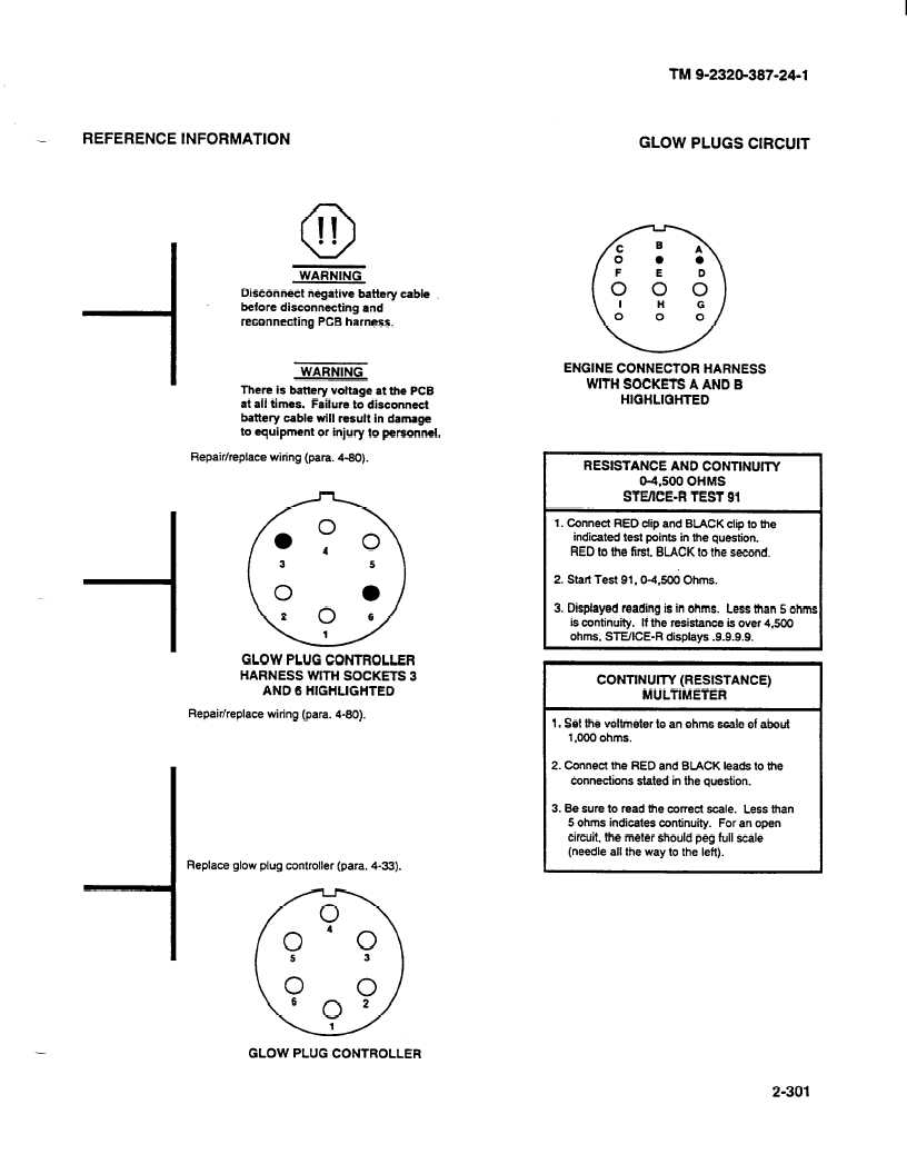
REFERENCE INFORMATION
GLOW PLUGS CIRCUIT
Disconnect negative battery cable
before disconnecting and
reconnecting PCB harness.
I
WARNING
I
There is battery voltage at the PCB
at all times. Failure to disconnect
battery cable will result in damage
to equipment or injury to personnel.
Repair/replace
wiring (para. 4-80).
GLOW PLUG CONTROLLER
HARNESS WITH SOCKETS 3
AND 6 HIGHLIGHTED
Repair/replace wiring (para. 4-80).
Replace glow plug controller (para. 4-33).
0
0
4
0
0 ;> ; 6 o2 1
ENGINE CONNECTOR HARNESS
WITH SOCKETS A AND B
HIGHLIGHTED
I
RESISTANCE AND CONTlNUlTY
04.500 OHMS
STEIICE-R
TEST 91
1. Connect RED clip and BLACK clip to the
indicated test points in the question.
RED to the first, BLACK to the second.
2. Start Test 91.9-4.5Ou Ohms.
3. Displayed reading is in ohms. Less than 5 ohm
is continuity.
If the resistance is over 4.500
ohms, WE/ICE-R
displays .9.9.9.9.
I
CONTlNUlTY (RESISTANCE)
MULTIMETER
1. Set the voltmeter to an ohms scale of about
1 .fIOO ohms.
2. Connect the RED and BLACK leads to the
connections stated in the question.
3. Be sure to read the correct scale. Less than
5 ohms indicates continuity.
For an open
circuit, the meter should peg full scale
(needle all the way to the left).
GLOW PLUG CONTROLLER
2-301