TM 9-2320-387-24-l
REFERENCE INFORMATION
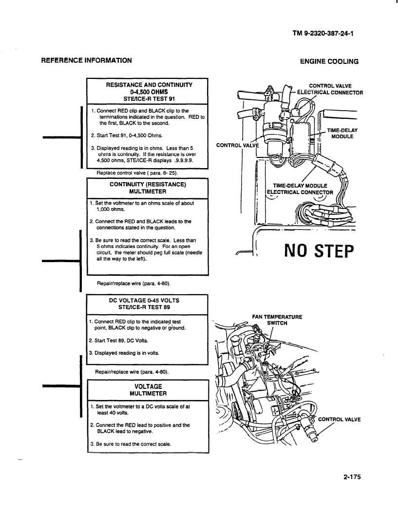
ENGINE COOLING
(I
RESISTANCE AND CONTINUITY
04,500 OHMS
STVICE-R TEST 91
1. Connect RED clip and BLACK clip to the
terminations indicated in the question.
RED to
the first, BLACK to the second.
2. Start Test 91.0-4.500
Ohms.
3. Displayed reading is in ohms. Less than 5
ohms is continuity.
If the resistance is over
4,500 ohms, SLUICE-R
displays
.9.9.9.9.
Replace control valve ( para. 8 25).
CONTINUITY (RESISTANCE)
MULTIMETER
1. Set the voltmeter to an ohms scale of about
1,000 ohms.
2. Connect the RED and BLACK leads to the
connections stated in the question.
3. Be sure to read the correct scale. Less than
5 ohms indicates continuity.
For an open
circuit, the meter should peg full scale (needle
all the way to the left).
Repair/replace wire (para. 4-80).
DC VOLTAGE O-45 VOLTS
STEKE-R
TEST 89
1, Connect RED clip to the indicated-test
point, BLACK clip to negative or ground.
2. Start Test 89. DC Volts.
3. Displayed reading is in volts.
Repair/replace wire (para. 4-80).
VOLTAGE
MULTIMETER
1. Set me voltmeter to a DC volts scale of at
least 40 volts.
2. Connect the RED lead to positive and the
BLACK lead to negative.
3. Be sure to read the correct scale.
I
CONTROL VALVE
w
t_ ELECTRICAL
CONNECTOR
P
-
5
.
.-,-
.’
v=i!
NO STEP
FAN TEMPERATURE
VALVE
2-175