TM 9-2320-280-20-2
3-79. FAN DRIVE FRICTION LINING REPLACEMENT
This task covers:
a. Removal
b. Installation
INITIAL SETUP:
Tools
General mechanic’s tool kit:
automotive (Appendix B, Item 1
Manual References
TM 9-2320-280-24P
Equipment Condition
Disconnect battery ground cable (para. 4-73).
WARNING
Prior to loosening screws on fan drive retaining plates, disconnect
fan drive hose from fan drive. Failure to do so may result in injury to
personnel or damage to equipment.
NOTE
It maybe necessary to apply compressed air to clutch adapter. This
disengages fan drive clutch to allow access to friction lining screws.
The fan drive hose may be modified to add the quick-disconnect.
Refer to Appendix D, Fig. D-94 for installation.
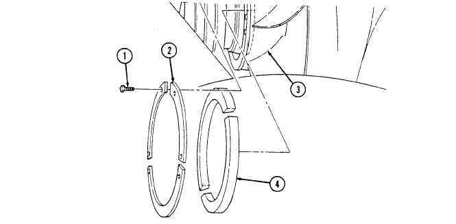
1. Remove six screws (1) and three retaining plates (2) from fan drive (3).
2. Remove friction lining (4) from fan drive (3).
1. Install friction lining (4) on fan drive (3).
2. Install three retaining plates (2) on on drive (3) with six screws (1). Tighten screws 1) to 22 lb-in. (2.5 Nom).
FOLLOW ON TASK: Connect battery ground cable (para. 4-73).
3-136