TM 9-2320-280-20-1
REFERENCE INFORMATION
Change 1 2-473
STEERING SYSTEM
Do not loosen slotted nut to install cotter pin. Loosening the nut
may result in damage to the equipment.
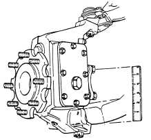
To check for proper operation of ball joints:
(i) Chock rear wheels front and back.
(ii) Raise front wheels about two inches off the ground and
support on a jack stand.
(a)Lower ball joints.
(iii) Mark a line across the head of the top bolt holding the steering
arm cover. Make sure the mark is parallel to the lower control
arm.
(iv) Put a prybar between the cover control arm and geared hub.
(v) Set a 6-inch ruler upright between the lower control arm and the
marked screw.
(vi) Push down the prybar to try to move the hub.
(vii) Measure movement in the hub assembly. If movement is more
than 1/8 inch (3 mm), replace lower ball joint (refer to para. 6-27).
(b) Upper ball joints.
(viii) Grasp top of tire and attempt to move it in and out.
(ix) Measure any movement at top outer edge of tire. Replace upper ball
joints if tire movement is 3/8 inch (10 mm) or more (refer to para. 6-26).
Check for looseness in idler arm and pitman
arm, refer to (para. 8-18 and 8-14). For
replacing center link refer to (para. 8-15). For
replacing tie rods refer to (para. 8-17).
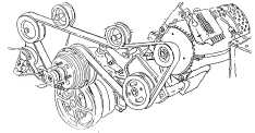
For adjusting the drivebelt tension, refer to (para. 3-82,
all except M1123 and "A2" vehicles), and replacing
the pulley, refer to (para 8-24).
CAUTION
M1123 and "A2"
CONFIGURATION