TM 9-2320-280-20-1
REFERENCE INFORMATION
Change 1 2-318.9
Ensure that alternator "AC" tap is functioning
correctly by measuring DC volts at wire 2A.
Reading should be between 9-16 Vdc. If this
voltage is not present, glowplug system will never
stop cycling.
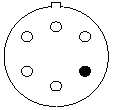
Refer to the functional flow schematic. If the
distribution box is shorted (continuity from pin 6 to
pin 3), the glowplug power relay will always be
energized and the glowplugs will always be
drawing current.
Since the glowplugs draw current
without the distribution box
connected, there must be a short in
the harness or a stuck relay in the
distribution box. If there were a
short in the harness directly to the
glowplugs, the glowplugs would
have burned out long ago and you
wouldn't be here. The only other
short in the harness that would
make the glowplugs turn on without
the distribution box installed would
show up as battery voltage at pin 6
of the controller's connector.
GLOWPLUGS
BATTERY CURRENT
MULTIMETER
1. Set the voltmeter to a DC volts scale of about 1
volt.
2. Connect the BLACK lead to the battery side of
the current shunt and the RED lead to the other
end of the current shunt.
3. Current shunt voltage is proportional to battery
current, 100 millivolts = 1000 amps. To get current,
multiply millivolts x 10.
BATTERY CURRENT
STE/ICE-R TEST 80
1. Start Test 80, battery current.
2. Displayed reading is in amps. The reading
will be greater then 30 amps, depending on
how many accessories you have on.
VOLTAGE
MULTIMETER
1. Set the voltmeter to a DC volts scale of at least
40 volts.
2. Connect the RED lead to positive and the
BLACK lead to negative.
3. Be sure to read the correct scale.
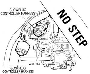
Check the end of the harness at the distribution box,
glowplugs, etc. for shorts. Repair whatever you can. If
you don't see anything wrong, the short must be in the
main body of the harness, which means that you have
to replace the harness.
For repair or replacement of wiring, refer to (para. 4-85).
Replace distribution box, refer to (para. 4-5.1).
6
1
2
3
4
5
Glowplug Controller
Harness Schematic
0-45 DC VOLTS
STE/ICE-R TEST 89
1. Connect RED clip to the indicated test point,
BLACK clip to negative or ground.
2. Start Test 89, DC volts.
3. Displayed reading is in volts.
Disconnect negative battery cable before discon-
necting and reconnecting distribution box harness.
There is battery voltage at the distribution box at all
times. Failure to disconnect battery cable will result in
damage to equipment or injury to personnel.
WARNING
NOTE