TM 9-2320-280-20-1
REFERENCE INFORMATION
ALTERNATOR
Change 1 2-219
1. Connect RED clip to the indicated test point,
BLACK clip to negative or ground.
2. Start Test 89, DC volts.
3. Displayed reading is in volts.
0-45 DC VOLTS
STE/ICE-R TEST 89
NOTE
For 60 amp Prestolite alternator, go to B, page 2-204.
For 100 amp Prestolite alternator, go to C, page 2-208.
For 200 amp Prestolite alternator, go to D, page 2-212.
For 200 amp single voltage Niehoff alternator,
continue with E.
For 100 amp single voltage Niehoff alternator, go to F,
page 2-222.
For 100 amp dual voltage Niehoff alternator, go to F.1,
page 2-224.2.
For 200 amp dual voltage Niehoff alternator, go to G,
page 2-224.6.
For 400 amp dual voltage Niehoff alternator, go to H,
page 2-224.10.
NOTE
The regulator for this model alternator has
overvoltage protection. Any output voltage over
30.5 volts is an overvoltage.
Output voltage of 26-30.5 is acceptable for this
alternator.
1. Start test 10, Engine RPM.
2. Crank or start the engine. Displayed reading is
RPM. Engine RPM should be 1200-1500.
ENGINE RPM
STE/ICE-R TEST 10
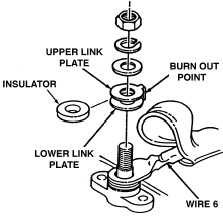
FUSIBLE LINK REPLACEMENT
1. Disconnect battery ground cable.
2. Remove boot from alternator output terminal.
3. Remove nut, lockwasher, washers, and fusible link from
terminal.
4. Inspect fusible link.
5. Replace fusible link if damaged or appears burned.
6. Connect battery ground cable.